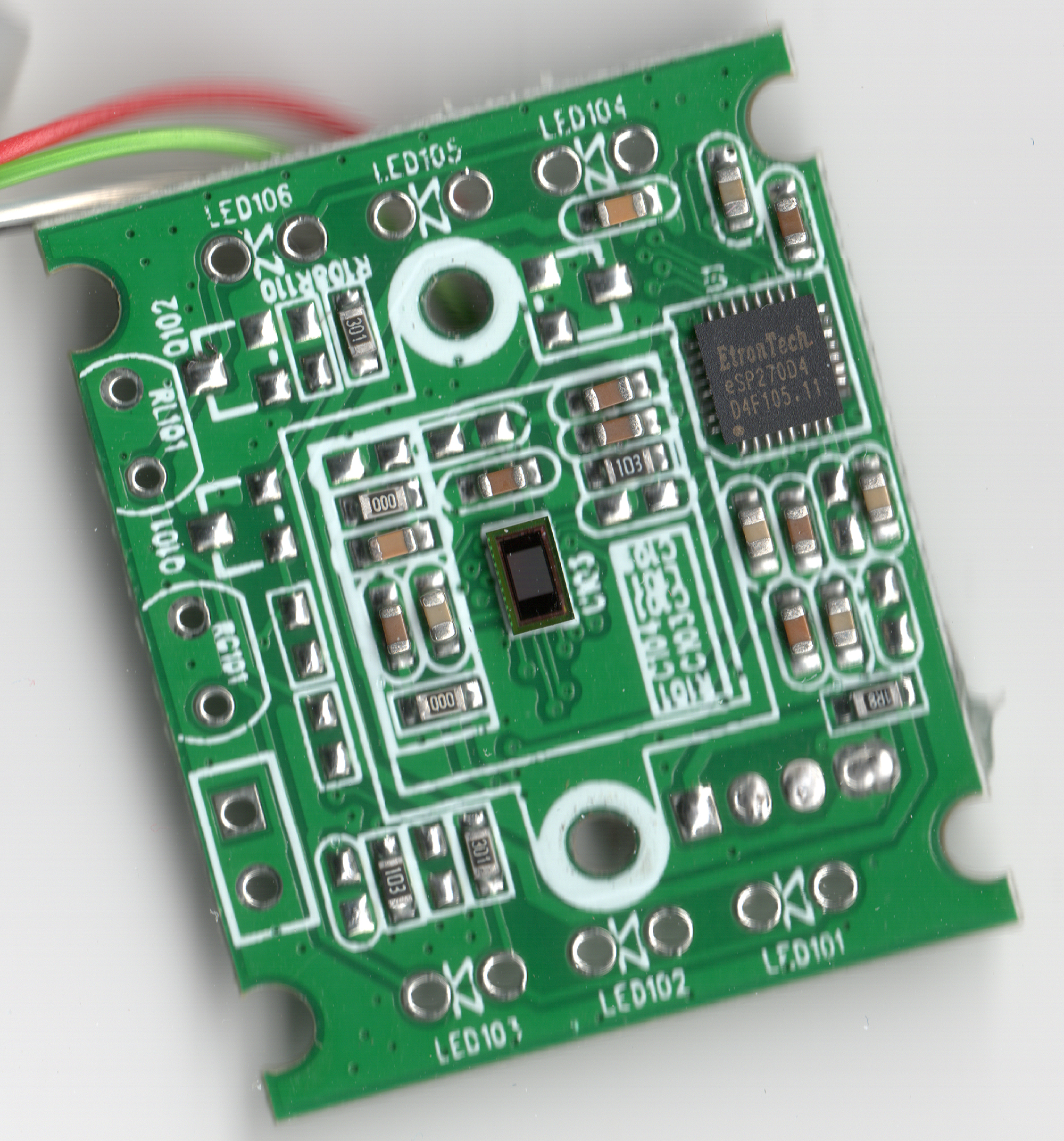
I took apart this $3 webcam from the dollar store. It has an EtronTech chip with the numbers eSP270D4 D4F105.11 printed on it. I took a high resolution scan of it because it was so tiny and hard to read.
I still haven’t found drivers for it but I fear it’s just a dud. Like most cheap cameras that claim to be a Megapixel or more, it is in fact a 0.3 Megapixel CCD. That’s the same resolution as old televisions, and it’s quite blurry. It comes zoomed in. There’s no way to adjust the zoom. It’s just a zoomed in plastic lens screwed directly to the CCD. Unscrewing the back removes the lens from the CCD.
Here’s a picture of the circuit board.
This is interesting.
I also took apart the module I had just received from China.
Yours seems to have more SMD components around the sensor chip.
Mine has 6, but from your photo, yours has 10 in that box’d-in area.
I wonder if there are slight differences.
The China seller on Amazon stated it’s a 5MPixel camera, and had software to offer that made the photos higher resolution, but wanted more $$ for this CD 🙂
The seller also claimed it doesn’t need a driver if it’s used with Windows 7 or 8.1
(I don’t remember if Win XP didn’t need any.)
I haven’t tried using it yet, but suspect it’s VERY low resolution, given the small size of the sensor chip.
What operating system are you using it with?
I have Windows 8.1 Pro 64-bit and can also try a “live” Linux install, using an ISO image of FatDog64 Linux OS.
The board that it’s on, seems to also have other part options, like 6 LED’s (I’m guessing InfraRED for night lighting, or white LED’s for normal lighting)
With trace-patterns for extra transistors (Q101 and Q102), most likely for controlling the brightness of the LED’s.
Plus there’s a trace pattern for what looks like a Surface Mount Device (SMD) serial ROM chip. (8-pins) designated as U2 on the silk-screen printing. This usually is where the ‘Driver’ or PnP device info was meant to be stored, so the USB port knows what it is.
If you’re wondering how I deduce that, … it’s the wiring of that 8-pin pattern that shows me. I’ve had experience with these before.
There’s also mention of ‘RL102’ and ‘RG101’
I’m not sure what these may be, but they look like they’re connected to the trace-patterns of the two transistors, and may be switch pattern wiring. (Not sure)
If I get curious, I may delve deeper into the wiring of all of this.
I’m just amazed someone else on the web also opened this module, and even purchased one, as well as I.
And here I am amazed that anyone else cared that I opened one. Thanks for your input. You’ve taught me a thing or two and I appreciate that.
I’m amazed again, that you replied…! 🙂
I don’t know what I ‘taught’ you about it, but I’m happy I could give you any information about it, at all, that you didn’t already know. 😉
I’ve also found the IC company online, and verified the controller chip inside this camera is JUST VGA. 640×480,
no matter what resolution the imager used is.
I tested the camera, on my Windows 8.1 PC, and mine, as well, is out-of-focus, with no way to adjust it.
I used the built-in App on Win8.1 called ‘Camera’ to see how it worked.
It’s recognized as a USB2.0 Camera, with the Microsoft driver in that OS.
I’ve contacted the seller on the Amazon website, and told him they’re misleading the public saying it’s a 5 Mega-Pixel resolution sensor. I may also let Amazon know.
Oh well..!
Hey, … I noticed your other posts about the Western Digital product, with the bad ROM chip.
I saw that you’re knowledgable about Linux, and ‘programming’ in-general, and I’d like to let you know of another product you may like to take-apart and even re-program.
It’s a small travel router, battery operated, also USB powered, that has a built-in DLNA and Samba video streaming, and file server within the firmware that comes with it.
HooToo TripMate Nano Wireless N Pocket Travel Router
HT-TM02 selling on Amazon for $14.99 as of now (date of this post)
http://www.amazon.com/HooToo®-TripMate-Wireless-Powered-Storage/dp/B00HZWOQZ6/ref=pd_cp_pc_2
But here’s the fun part…someone on the OpenWRT forums has ported OpenWRT to it, and has opened all of its functions and features. (Sort-of..)
They said they just made a simple setup for it so far, but more builds and packages can be created (compiled) to work within it. Such as using it’s USB 2.0 port for a camera or other devices like a USB HDTV Tuner.
With the stock firmware I was able to attach a WD 1TB 2.5 inch hard drive, and have it file serve to my iPad2.
Their iPad App is not the best, but if you have a separate one, it does play videos well.
I’ve tried the install this OpenWRT person created, and it does work…giving MANY more features than the original firmware had. Thru the LuCI console he made.
The original post, from the person to ‘crack’ into it, is here…
https://forum.openwrt.org/viewtopic.php?id=53014
His builds and packages, with the info on them, is here…
https://github.com/wingspinner/HooToo-Tripmate-HT-TM02-OpenWRT
But I don’t know how to use Linux to create the other builds for the camera or other features I wanted the USB port to see, let-alone working with the raw OpenWRT language. 🙂
If you understand it all, you could have the source code from the OpenWRT builds, compiled to work with this device.
I’d like to learn how to do that myself.
Eventually I may succeed, but I could be very old by then. Haha..! 🙂
The persons original post on the forum explains what’s inside the device. It’s selling quite well on Amazon, after this OpenWRT porting, and people really like its RF power, from just a simple small internal chip antenna.
There’s a board trace pattern to also attach a connector for an external antenna. With the little chip antenna, it transmits around 30 to 60 feet. (Depending on obstacles)
Not bad huh?!?
That AP is really affordable! I think I’ll get one!
Yes I know some coding so maybe I could help if I had a hardware spec to go from, or any idea how to make a Linux driver.
All the Linux source code is already made 🙂
It just needs to be compiled for the RT5350 chip inside it.
The original poster on the OpenWRT site said what was needed in one of his posts on the second page, to put a camera ‘driver’ on the device.
Since then, I’ve looked around, and found these on the web, dealing with stuff like this, but it’s not compiled. It’s just the source code.
http://www.ideasonboard.org/uvc/#download
http://git.linuxtv.org/cgit.cgi/
https://wikidevi.com/wiki/Ralink_RT5350
(There’s a newer source-code on the HooToo site, although not complete, and I’ve got the master one from RaLink, if I can’t find the original search result from Google, I can link you to it on my OneDrive account.)
Most source-code to do anything with OpenWRT can be found at their main site, thru the search function.
https://openwrt.org
And the main GitHub site
https://github.com
As far as I understand, when the source is placed on the Linux computer, special commands along with a ‘MakeFile’ are activated to create builds, and BIN packages that are the actual firmware, or drivers used, specific to the chip on the board using them.
I only understand a small, simple aspect of it all, but everything needed is online, downloadable from the sites listed above, as well as other sites dealing with these same functions.
The original poster said he’s made several of them, but I didn’t see any for the DLNA or Samba server, or the camera or TV stuff.
But it does exist, I’m sure, because I’ve seen other posts on the OpenWRT forum dealing with similar circuits.
The ‘BIN packages’ need to be customized for the specific board, so the pins on the chip dealing with the GPIO’s will work properly. (At least that’s what I gather from it)
In other words, the firmware from a HooToo IP camera can’t be used on these router boards because the GPIO pins may be setup differently.
Likewise for other HooToo products, or other companies using the same main SoC chip.
Too bad the firmware from these other devices can’t be ‘dissected’ and parts of it used as-is. It would have been easier to ‘copy/paste’ what’s needed for other applications, from each firmware package. 🙂
There’s a lot of information on that original posters thread, but it’s still not complete, and he didn’t explain much. He was assuming the readers already knew how to use the information.
He’s also not returned back to answer the newer posts there, so I don’t know if he’s interested any longer.
I wanted to include the file-server DLNA and Samba, as well as all the router Bridging packages, with the Camera and TV tuner drivers.
The camera posted about here may not be listed in that ‘UVC’ link, 🙂 but many more are already available on the Linux sites…
Here…
http://www.ideasonboard.org/uvc/#download
…and here…
http://git.linuxtv.org/cgit.cgi/
All this stuff makes my head swim in it’s own juices…I’m more of a hardware guy. 🙂
By the way, I forgot to let you know…
I have the original RT5350 SoC DataSheet.
Nearly 300 pages in PDF format 🙂
Good to know. I bought one of those HooToo devices so perhaps I’ll need to look at that some day.
Awesome..!
I’m sure you’ll be impressed with it.
Maybe not so much the iPad App for it, but the router is impressive by itself.
Until the company remakes the App, I hope you have one that can test-out the file server and streaming video functionality. Their App works, it’s just not playing all video file-types. The older version did, but didn’t have the codec for all the audio streams (Dolby …etc)
If you have any questions on its setup or usage, just post here, or eMail me at the address I used for this blog.
Looking forward to hearing your opinions about it. 🙂
Hi..! 🙂
I’m checking in with ya, to see if you’ve received the HooToo TM02 Travel Router yet.
If you have, were you able to test it out yet?
How ya like it?
Any chance you’ll try the OpenWRT on it?
If you want to know how to open it, if you haven’t already, …let me know.
Awaiting your reply… 😉
Bye for now..!
I received it last night and so far the default firmware seems to be no good at all. It won’t work as an access point. Odd…
I’ll fiddle with it further. Chances are pretty good that I’ll put openwrt or something on it.
That IS odd.
Either you received a bad unit, or you’re not setting it up correctly.
Were you able to access the web User-Interface via the Ethernet port or wifi using 10.10.10.254
The instruction page sent with it, is a bit ‘unclear’ 🙂
But the unit should at least let you see the web page style UI
so you can make your settings.
If you post a negative review on the Amazon site, the customer service rep may send you a free 2nd unit to try.
You can send an eMail to them too, and they’ll respond with help on how to set it up.
support@hootoo.com
I can give ya some help too, if you need. 🙂
It works and I get the interface, but it refuses to properly bridge my LAN to the WiFi.
When I change settings in the interface, sometimes they are applied incorrectly and the password I set or 11111111 both fail to authenticate. At that point I have to reset the unit to defaults and try again.
Even with default settings it doesn’t bridge my LAN to WiFi.
It seems as if the firmware is screwy.
I don’t have a lot of time to play with it today.
It’s ‘bridge’ function is from the wired Ethernet …usually … to make a hotel’s single wired Ethernet become a wifi connection to more than one device.
It will accept a wireless signal to bridge, but there’s a procedure, and it’s limited in its use with the stock firmware. The switch near the micro USB power input plug plays a part in it, to open that option in the UI.
So if you’re trying to have it ‘lock into’ your router via a wifi connection, that won’t work easily, with its stock firmware. But the OpenWRT is supposed to open that feature, allowing more bridging options too.
I was trying to bridge my ISP’s wireless public HotSpot thru it, but was told by The HooToo tech, it doesn’t work that way with their firmware…
But with the OpenWRT, it’s supposed to be possible.
***Also… If you change the network password, and your wireless device doesn’t re-connect to it…
You may need to tell your device to ‘forget’ it’s past connection to it. If you use an iDevice I can tell you how that’s done.
This same thing happened to me, and the techs let me know I needed to use the ‘forget network connection’ option for that older setting, on my device (iPad) so the wireless device will again ask you for its new changed network connection password.
The OpenWRT firmware will allow many more options, but if you want to just test stuff, when you have more time… you can call the tech I spoke to, directly, to help you understand some of the settings on this firmware.
His name is Mike Lam and his direct phone # is
408-215-9705 (no, this isn’t me 🙂 …although I’ll be happy to help you too, even though I don’t work for them)
I’m happy it’s at least working, so far, and you were able to get to the UI.
Speak to you when you’re less busy… 🙂
Till then…bye for now.
I think you misunderstand. To connect a LAN interface to WiFi, a router bridges the LAN and WiFi. I’m not talking about repeater functionality.
I’m saying this thing refuses to function as an AP, even though the settings seem to indicate it should work.
Thanks for the help.
Oops, sorry…I guess I did misunderstand.
The tech at the direct phone# I gave you, will let you know if there’s a fault with the device, or if it’s simply settings your not using correctly.
They’re on the West Coast, so if you do call… adjust your call-time for their time-zone. Or…eMail them at the support@hootoo.com
But the tech at the phone # may be quicker.
I wish I could help further, but I’m not fully understanding your issue. 🙁
If I connect my HooToo thru it’s Ethernet to my router, I do get wireless to my internet, but you may be trying something more sophisticated than I was using it for.
I thought AP (Access Point) was like a standard router would be, but I guess I’m wrong.
I’m sure, if their stock firmware doesn’t support your use, the OpenWRT will. The SoC chip used in it, is also used in many other standard routers too.
Please keep me informed of your outcome.
A few quick pointers about it…
The default network password is 11111111
(8 x #1)
That’s to enter into wifi mode with your iPad or other device, when your device asks for it, to allow connection.
There’s no default password needed to enter the web-style UI
(Name = admin with the password-field left blank)
All lowercase letters in the name.
You should at least be able to get this far.
If not, let me know…also support@hootoo.com
What are you using to power the TM02
I used my iPad power adapter/charger USB 5v out.
Before you try connecting any device to the full-sized USB port, make sure the unit comes on and you can get the UI up
It tasks about 20 to 30 seconds for the unit to fully boot-up and stabilize, after it’s powered.
🙂 my iPad autocorrect changed ‘takes’ to ‘tasks’ … Haha
In the sentence…
‘…It tasks about 20 to 30 seconds for the unit to fully boot-up and stabilize, after it’s powered. …’
I’m sure you understood, but I wanted to be sure. 😉
If I’m understanding your bridging needs with this…
You’re trying to bridge the computers on your LAN (Local Area Network) and your Wireless internet connection, thru the HooToo?
Even if I’m still wrong, I’ve seen people’s questions and the answers they got…on that Amazon review section, in the separate area where they have the Q and A from customers.
They did have bridging answers there.
That can be a quick way to see if anyone else wanted to do what you wanted, too, until you can contact the SunValleyTek technician about it.
Anyway, …I’m feeling bad if I advised you to get this and you can’t do anything you wanted with it. 🙁
I’ll stop bothering you about it.
Hoping you find the solution soon.
Ean, I didn’t realize you’re in Toronto, Ontario, Canada
Here I am giving you a techs phone # from USA to call.
If you’d like, I can be the bridge to them, from you…
if you like me to ask the tech a question and relay the answers to you, by eMail, or this blog.
I’m in the USA.
OK…that’s my last post about this, unless I hear from you.
:-/
I hate being annoying, sorry if …
Thanks very much for all of your help.
I received a reply from my 1-star Amazon review. The Canadian distributor replaced my HooToo at their cost.
I’ll tinker with it when I get the chance and I’ll let you know if I have any success making it work with a webcam driver on the USB port if I put OpenWRT on it.
That’s great 🙂
I wanted to post I found out the stock firmware treats the HooToo Ethernet port as a WAN, not LAN port.
But the OpenWRT may be able to reprogram that, or bridge the LAN to the WAN port, if it’s a hardware wiring issue from the SoC. (I’m not sure of that last statement though)
I didn’t want to bother you about it anymore, here, unless you replied. I thought I may have caused you to purchase another wasted circuit, as the camera was to you.
Anyway, if you need any info regarding the HooToo on-board serial console, let me know.
I’m using micro-clips to attach the Prolific USB to TTL serial cable output wires, to the Nano, rather than soldering it to the board. I like keeping the original circuit clean of soldering stuff to it…unless necessary…but that’s just me.
If you flash the correct file to the Nano, you may not even need that serial cable. I got it because I originally thought I had ‘bricked’ the Nano, but didn’t realize it was supposed to connect directly to my computer (by Ethernet) instead of thru the router, and thought it wasn’t working as it should when I didn’t get the LuCI console up. 🙂
I don’t think the other OpenWRT packages need the serial cable to program into the Nano, but I haven’t gotten that far to be sure. There’s a LuCI section that allows adding more packages.
You’ll see how much more you can do with it when you get the OpenWRT on it. I don’t fully understand it all, but was impressed by what options showed.
Have fun..!
I’ll be here, waiting to see what happened.
Ean, the author (wingspinner), of that OpenWRT code for the HooToo Nano router, is back answering questions again.
If you posted a question and haven’t logged-in for awhile, the site just sends one notification until you log-in again.
…you won’t get any additional notifications after the first you received, if you post and someone else posted afterwards, before wingspinner answered…
So, if you’re still working on it, but was waiting for his reply to continue, now’s the time to ask him questions. 🙂
Thanks. I have it working withOpenWRT now. Its great! Haven’t tried anything with the camera yet.
That’s awesome…I’m glad you got it working the way you wanted it.
I found out, with the OpenWRT installed, the WAN goes thru WiFi, and the LAN is ported thru the Ethernet port. (With stock firmware the Ethernet port is WAN only)
wingspinner will be updating the code he made soon too. I don’t know what he’ll add, but at least he’s back working on it again.
When you get the camera functioning I’ll be here to try it too… 🙂 … Thanks for continuing with it.
Did you learn the OpenWRT language, or just used what was available and compiled it again?
No need to answer now, I was just curious.
Oh I just tried the ROM out to see if it would make the TM02 more useful.
I’ll have to see if I get some time if I can compile the camera driver sources in busybox or whatever OpenWRT is running.
The “ROM”…?
Did you substitute the 8MB ROM for a 16MB one, to put more coding in the Nano?
I’m confused… 🙂
At least the one they sent you as a replacement works now.
Please keep me informed on your progress with it.
This little device has gotten VERY popular on the Amazon site, with AND without OpenWRT on it..! 😉
People often use ROM to refer to a ROM image file colloquially. That’s what I was doing. Sorry if I made you think I was talking about hardware. I meant that I have OpenWrt on the HooToo.
I realized that after I posted the reply, but couldn’t delete it. 🙂
Hi Ean,
I don’t know if you looked at wingspinner’s thread recently,
But he posted how his original default trunk packages were altered by the OpenWRT ‘powers that be’ where it originally supported even USB cameras already…
https://forum.openwrt.org/viewtopic.php?pid=261438#p261438
…maybe the recent download of his files have this altered set of packages.
(Post 67)
Post 66 may be interesting to you too,
Unless you’ve read them already.
Here’s a summary of the latest post#67 …
Checking the latest trunk build it appears the OpenWRT powers that be arbitrarily removed all the default packages I had defined for the default build. My intent was to save users time by selecting all the correct kernel modules that made a complete system (i.e. support for all the built-in hardware). What’s there now won’t do much for you. You can add them back in at run-time but it’s not as efficient in my opinion. Here is the original configuration for reference:
define Profile/HT-TM02
NAME:=HOOTOO HT-TM02
PACKAGES:=\
wpad-mini \
kmod-ledtrig-netdev kmod-ledtrig-timer kmod-leds-gpio kmod-ledtrig-default-on \
kmod-usb-core kmod-usb-ohci kmod-usb2 kmod-usb-net usbutils \
kmod-scsi-core kmod-scsi-generic kmod-fs-ext4 \
kmod-usb-storage kmod-usb-storage-extras block-mount \
kmod-usb-serial kmod-usb-serial-ftdi kmod-gpio-button-hotplug \
kmod-nls-cp437 kmod-nls-iso8859-1 kmod-nls-utf8 luci luci-mod-admin-full \
kmod-app-samba luci-theme-openwrt luci-proto-relay relayd nano \
fstools
endef
I’ll have to keep that in mind. Haven’t had the time to experiment with it lately. Sorry if you’re hoping for something soon in terms of a driver for the camera.
🙂
Don’t worry about it. I understand that this isn’t your first priority. I can wait. 😉
I just wanted to let you know what he posted, in case you’ve never looked at that thread.
hi… Ean and Tiny Camera…. I got here looking for solution to this cheap webcam similar to yours ….highly zoomed in 🙁 …. did you guys find any way out…plz reply 🙂 thanxs
There is no “solution” to fix the zoom.
The lens is permanently focused that way. It’s a tiny plastic lens permanently mounted to a really crappy sensor (VGA CCD).
Hi umesh (and Ean).
I found an old USB 1.0 webCam I have, that I can remove the lens mounting assembly from, and may experiment with mounting it to this other camera… but Ean is correct, it’s really limited to what can be done to ‘solve’ this issue.
Is your image from this original tiny camera out of focus too?
(Mine is)
(My lens assembly is mounted by screws that can be removed, on both camera boards)
This other lens-mount, w/ lens, is also focus-able…
..unlike the original tiny-camera mentioned on this blog.
I’m more amazed you found this blog-site about this little camera. We three may be the only ones who purchased it..Ha Ha..!
Search engines never cease to amaze me.
Hi Ean, how have you been?
I’ve figured out how to add the extra camera packages, as well as other packages, to the HooToo Nano for OpenWRT, without needing to re-compile the entire firmware file…but it needs internet access for that.
I needed to bridge my routers wifi signal to the HooToo Nano and I seem to be missing (not understanding) the basics of that from within the LuCI console.
I wanted to use the Ethernet port of the HooToo, to go to my PC, while bridging my router to the HooToo, thru its wifi connection, so I can access the internet and use my PC to add the OpenWRT packages.
Have you figured out how to set this bridging option, with OpenWRT and LuCI..?
Any help will be greatly appreciated 🙂
You want to do this? http://wiki.openwrt.org/doc/recipes/bridgedclient
🙂
Hi Ean, at this point I’m not sure if that’s what I want.
🙂
There’s no mention of the LuCi Graphical User Interface on that link, just text based config files.
I guess it’s what I want, … if it will allow the HooToo to connect to my original routers WiFi signal, or even a HotSpot WiFi signal, and bridge it to the Ethernet port of the HooToo, going to my PC, so I can access the internet and install the other Linux packages I wanted to try, installing it thru the LuCI UI.
When I go to the WiFi section of LuCI, and use the ‘SCAN’ option to select my routers wireless signal, enter the security key and any other info needed to connect, I don’t know of there’s any other stuff that needs to be added or changed with the other settings in LuCI, so it can connect.
I’ve tried several different things, but they just wind-up shutting down the WiFi or even both LAN and WiFi ports, and I need to use the serial console to reset it all with a ‘firstboot’ command.
I don’t see any LuCI ‘walk-thru’ explaining what to do on the OpenWRT site…step-by-step.
I’m sure it’s something so stupidly simple I’m not understanding, or just some step I’m doing that may not be needed to do, that’s stopping this from working.
If there’s LuCI to do it, why is the OpenWRT website just showing the text-based setup?
It’s really confusing.
Thanks for your reply.
Maybe in a few more months I’ll figure it all out 🙂
In the interface, set up your WiFi as you have been doing but do that LAST.
First: Set your LAN IP range to 192.168.2.1 or something NOT used by your home router’s IP range.
Second: Create a new interface of type bridge like this one: http://imgur.com/hu6WB90
Third: Scan and configure your WiFi as a client to your home router.
I’m currently typing to you from just such a set-up.
Hope this helps.
Thanks Ean. 🙂
I’m thinking what may have kept it from working before was, I did the 3rd step before changing the LAN to another different IP, or may have tried changing one of the other advanced settings, or others, when it wasn’t needed.
I’ll try this soon.
Hey, I just noticed there were zero(0) views when I first looked at the photo you put online, then, soon after there were 4 views of it.
I wouldn’t be surprised if others are monitoring your blog on this TinyCamera section, just for this info on the HooToo TravelMate Nano-Router and the OpenWRT info we were writing about.
It wasn’t me upping the view-count…I tried seeing if simply ‘refreshing’ the screen with the browser made the view-count go up, but it didn’t. So others are monitoring your blog for this information. …Amazing..!..the power of search engines…! 🙂
Would you mind if I posted a link to this on the OpenWRT site?
If this works for me, I’m sure others would want to know about it too.
Yeah, if it will help someone please do.
Oh…one last question.
How do you like this little Nano-Router, now that it has OpenWRT on it?
Does it do everything you wanted from it?
By the way…
The paths of the packages, that get loaded by LuCI, has changed. It needs to be corrected in the LuCI config section page, so it knows where to look online.
(They added ‘generic’ between the /ramips/packages/)
Here’s a part of the post mentioning it on the thread made by wingspinner from the OpenWRT, in case you never saw it.
—
“…It appears that the default path to the packages as of 2/8/15 no longer matches the path in the 42649 image file.
The GENERIC folder is missing. The new paths are as follows:
src/gz chaos_calmer_base http://downloads.openwrt.org/snapshots/trunk/ramips/generic/packages/base
src/gz chaos_calmer_luci http://downloads.openwrt.org/snapshots/trunk/ramips/generic/packages/luci
src/gz chaos_calmer_management http://downloads.openwrt.org/snapshots/trunk/ramips/generic/packages/management
src/gz chaos_calmer_packages http://downloads.openwrt.org/snapshots/trunk/ramips/generic/packages/packages
src/gz chaos_calmer_routing http://downloads.openwrt.org/snapshots/trunk/ramips/generic/packages/routing
src/gz chaos_calmer_telephony http://downloads.openwrt.org/snapshots/trunk/ramips/generic/packages/telephony
…”
—
The entire thread is here… (Starting at page 1)
https://forum.openwrt.org/viewtopic.php?id=53014
I like it fine. It’s a configurable little network device. That’s all I really wanted. I used to have some ASUS tiny device about the same size but a little longer and I gave it to an ex. So I wanted a replacement in case I travel, really.
Re: the folder issue – I noticed that too. I updated my Asus RT-N10+ (b) router to OpenWRT from an old DD-WRT build and to get opgk to work I had to edit /etc/opkg.conf and change it to /ramips/generic/packages/ as well.
Seems like someone deleted all of the package folders at OpenWRT for some reason. Fairly careless! Why not create a symlink so you don’t break everything!
I don’t know if this will help you, but that webcam was made by the Kisonli company in guangdon china. They sell them wholesale. Here’s a link. http://kisonli.en.alibaba.com/product/1970303689-800140236/USB_camera_module_usb_cam_module.html
It comes in different flavors of lenses, LEDs, etc. They have the specs on each one.
That looks like a much nicer lens assembly on that one.
Thanks for sharing.
Hi Ean
I don’t know what happend at my last mess-up, when I tried this, but I can’t even issue the ‘firstboot’ command in the serial console to reset everything now.
The boot loader goes to the watchdog section, loads the USB drivers for the Hub and USB file system (usbcore) then stops after it loads the SCSI subsystem and initialized it.
Then stays there without continuing to load the Ethernet drivers and other stuff.
After it stays like that for a while, it then starts the reboot sequence over, after 20 or 30 seconds, ending at the same place, over and over again.
I can’t get to the section in the BootLoader that accepts the ‘firstboot’ command.
It’s as if something got erased in the BootLoader sequence code.
This isn’t in any way your fault, if you’re thinking that. 🙂
It’s from the last time I screwed up when I was trying my settings several days ago.
I need to see what went wrong.
This never happened before.
I was always able to reset it all.
I have another Nano TM02 with OpenWRT on it, and I’ll try your info soon, on that one.
It’s a good thing I have this USB serial cable, or I’d never know what happened with the boot loader.
—-
To: Ken Bertschy
Thanks for finding the original manufacturer of that tiny camera.
I saw the specs of the different builds they make.
Seems there are a large range of imagers from the one we have of 640×480 resolution, all the way up to 10 Mpixel.
The other circuitry trace patterns also support a microphone…very interesting..!
Seeing that other lens system on there, I’m guessing if I can put my old USB 1.0 camera lens on this one, I may get the focus to be better, and not so ‘zoom’d in’ 🙂
Maybe one day I’ll experiment with it, and see.
Oh wow. Bricked so bad you can’t even enter commands to JTAG (serial) flash it?
That may be hard to recover short of owning a chip flasher and re-writing the boot manually. Even then you’d have to get your hands on the boot ROM.
The last time something like that happened, it turned out my WD Live had somehow lost a flash cell and re-flashing it failed right in the middle. It would cycle boot over and over.
I was still able to get to the point where it would try to re-flash but the flash failed with an error. WD simply replaced the unit. (Which is still garbage, even after being replaced. It constantly freezes and needs to be power cycled.)
I’m not worried, I have a Willem EPROM programmer, (v4.1) and wingspinner said he was able to program the chip ‘in-circuit’ (without needing to remove it) using one of those 8-pin clips that connect around the chip leads.
(Sold on eBay from China for around $8 or less)
If it turns out the chip is dead on one of its cells, I found places selling new ones.
If I do need to replace it, I may get the 16 MB version.
Wingspinner verified he was able to upgrade it to a 16 MB chip. Just the RAM can’t be upgraded to 64 MB because there’s no provision for it (trace line) to support the extra memory blocks, on the board.
But the EPROM does work for 16 MB.
Very strange though, how it screwed up. 🙂
I still have things to try with it first.
I have the original coding before it was changed, plus I can always copy the second TM02 ROM-chips code.
I just need to see why my settings keep shutting down the wifi signal when I try bridging.
I still have the other TM02 to try, and I just tried the settings, but there are other settings I’m not sure of when I scan my routers wifi signal, and also when I create the second interface.
Do I create another wifi interface, or check-box the ‘replace’ the wifi?
Because when I replace with the bridge, it seems to shutoff the wifi signal.
Should I keep the same channel and name of the original routers wifi name, or change it?
Watch me mess-up this second TM02 also… 🙂
Amazing…!
I was able to get back into the 1st seemingly bricked TM02, and use LuCI to reload the original working config I had.
Stupid me, forgot I had my PC set with a static IP to my router.
OK…no harm..! 🙂
I still don’t know why the BootLoader didn’t finish the boot sequence, and made it look like it was bricked.
Even with the second TM02, the boot sequence finished, and loaded the Ethernet drivers…even though my PC still had that static IP set on it.
When I saw that one also didn’t connect to my PC thru Ethernet, that’s when I remembered I had the static IP set on my PC 🙂 Oy..!
I was ‘almost’ hoping it WAS bricked…it would’ve given me an excuse to get the 16MB ROM replacement. Ha-ha!
Wow! Good news that it’s working.
Yeah you have to keep an eye on your network settings while messing around with this stuff. It’s a lot to remember and check, I suppose.
I suppose a 16MB (or 32?) Flash might be helpful. My home router has 32MB ROM and 16MB RAM. Easier to flash with OpenWRT because you don’t have to use a USB drive to extend the storage during install. Of course that’s good because my router doesn’t have a USB port either. (Chip may have a USB header.)
Wingspinner said the 16MB ROM gives more room to load the packages to do more with the TM02.
I don’t know how much RAM is needed, using the 8MB ROM, but if there’s actually 32MB’s of RAM, and not much extra is needed as a ‘scratch-pad’ of memory, using the 8MB ROM, then there’s actually much more room left in RAM to fill-up with code, during the boot sequence, using more ROM space.
Eventually, when I figure-out all this stuff, I’m going to see how much coding (packages) I can put on there. Eventually I may get a 16MB ROM just to test.
Wingspinner did say, though, that something in the configuration needed to be altered in the firmware to accept a higher ROM size.
I’ll need to see what he mentioned about it in his thread. But for now, I’ll leave the 8MB ROM on there.
🙂
I think I know why the boot sequence wasn’t finishing on the 1st TM02.
When I messed-up the settings 2 or 3 weeks ago, it shut-down the wifi and Ethernet ports.
So, that coupled with me having the PC set with a static IP, gave the ‘illusion’ it was bricked.
It would have connected to the Ethernet without issue if I had the PC using the auto-IP configuration.
Hi Ean, I think this is making me insane 🙂
Every time I try this it shuts down the wifi signal on the TM02
Let me tell you my config on my home router setup.
My router already has a different IP other than the one on the TM02. Do I still need to change the one defaulting to 192.168.1.1 on the TM02 ?
Also, my router has the MAC filter on to only allow MAC#’s listed to connect.
I’m sure that must also be playing some part in this.
I even tried bridging the WiFi HotSpot of my ISP.
Their HotSpots are Open with no encryption, but I can’t connect to that either… My settings still make the TM02 lose the wifi output signal, shutting it off.
I think I just don’t understand what I’m supposed to do.
Like a brain freeze to all this.. 🙂
When I try to create a client, that’s when the wifi shuts off from the TM02
I’m obviously not comprehending this router bridge stuff.
SUCCESS…!!!
Don’t ask me how I got it…cause I’m still trying to figure out what I did…but I have it bridging my ISP’s WiFi HotSpot to my PC’s Ethernet port.
Maybe after I figure out what worked, I’ll attempt to try it with my home router 🙂
I DID need to uncheck the line that says it will replace wireless configuration unless that check-box is UNCHECKED.
Un-checking it created a new wireless connection?
(I don’t know…but my ISP’s login screen came up on my PC)
WOW…!!
Bless my stupid brain.
Now I need to see how I did it 😀